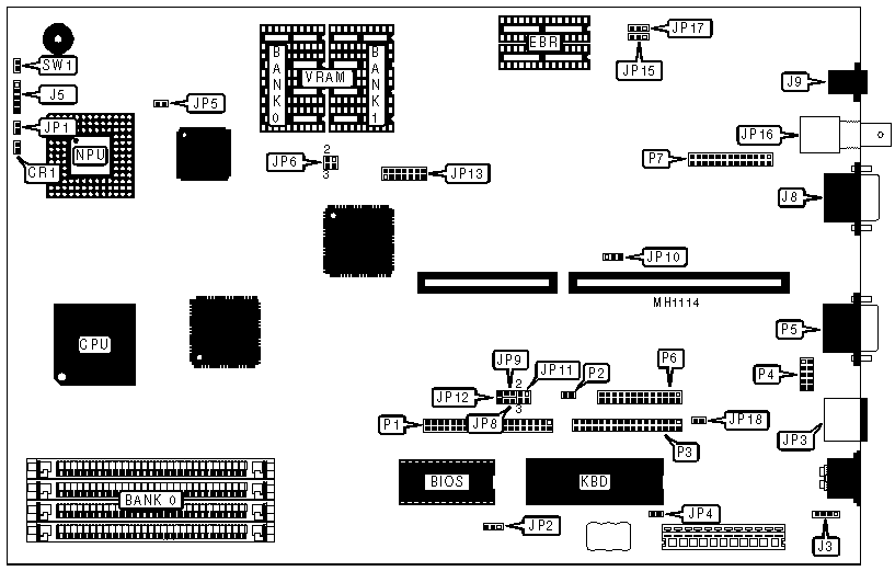
MULTIBEST INDUSTRIAL & MANUFACTURING, INC.
MultiLAN
|
Processor |
80386DX |
|
Processor Speed |
25/33MHz |
|
Chip Set |
OPTI |
|
Max. Onboard DRAM |
16MB |
|
Cache |
None |
|
BIOS |
AMI |
|
Dimensions |
330mm x 215mm |
|
I/O Options |
Ethernet interface (10 Base 2 & 10 Base T), floppy drive interface, IDE interface, bus mouse port, parallel port, serial ports (2), VGA feature connector |
|
NPU Options |
80387/3167 |

|
CONNECTIONS | |||
|
Purpose |
Location |
Purpose |
Location |
|
Turbo LED |
CR1 |
IDE interface |
P1 |
|
External battery |
J3 |
IDE interface LED |
P2 |
|
Power LED & keylock |
J5 |
Floppy disk interface |
P3 |
|
VGA port |
J8 |
Serial port 2 |
P4 |
|
10Base2 LAN port |
J9 |
Serial port 1 |
P5 |
|
Turbo switch |
JP1 |
Parallel port |
P6 |
|
Mouse port |
JP3 |
VGA feature pass through |
P7 |
|
10BaseT LAN port |
JP16 |
Reset switch |
SW1 |
|
Note:The Ethernet buffer RAM (EBR) is factory configured. | |||
|
USER CONFIGURABLE SETTINGS | |||
|
Function |
Jumper |
Position | |
| » |
CMOS memory normal operation |
JP2 |
pins 2 & 3 closed |
|
CMOS memory clear |
JP2 |
pins 1 & 2 closed | |
| » |
Monitor type select color |
JP4 |
Closed |
|
Monitor type select monochrome |
JP4 |
Open | |
| » |
VGA port enabled |
JP5 |
Open |
|
VGA port disabled |
JP5 |
Closed | |
| » |
Floppy drive interface precompensation mode normal |
JP8 |
Open |
|
Floppy drive interface precompensation mode alternate |
JP8 |
Closed | |
| » |
Floppy drive speed select single |
JP9 |
Open |
|
Floppy drive speed select dual |
JP9 |
Closed | |
| » |
Parallel port select LPT1 interrupt IRQ7 |
JP10 |
pins 2 & 3 closed |
|
Parallel port select LPT2 interrupt IRQ5 |
JP10 |
pins 1 & 2 closed | |
| » |
IDE interface enabled |
JP12 |
Open |
|
IDE interface disabled |
JP12 |
Closed | |
| » |
Factory configured - do not alter |
JP15 |
pins 1 & 2 closed |
| » |
Ethernet network interface select 10Base2 |
JP17 |
pins 1 & 2 closed |
| » |
Ethernet network interface select 10BaseT |
JP17 |
pins 2 & 3 closed |
| » |
Bus mouse port enabled |
JP18 |
Closed |
|
Bus mouse port disabled |
JP18 |
Open | |
|
DRAM CONFIGURATION | |
|
Size |
Bank 0 |
|
1MB |
(4) 256K x 9 |
|
4MB |
(4) 1M x 9 |
|
16MB |
(4) 4M x 9 |
|
VRAM CONFIGURATION | ||
|
Size |
Bank 0 |
Bank 1 |
|
512KB |
(4) 128K x 8 |
NONE |
|
1MB |
(4) 128K x 8 |
(4) 128K x 8 |
|
VRAM JUMPER CONFIGURATION | |
|
Size |
JP6 |
|
512KB |
pins 1 & 2 closed |
|
1MB |
pins 3 & 4 closed |
|
ETHERNET MODULE JUMPER CONFIGURATION | |
|
Function |
JP13 |
|
Ethernet enabled |
pins 1 & 2 closed |
|
Ethernet disabled |
pins 1 & 2 open |
|
INTERRUPT CONFIGURATION | ||||
|
Interrupt |
JP13 pins 7 & 8 |
JP13 pins 9 & 10 |
JP13 pins 11 &12 |
JP13 pins 13 & 14 |
|
IR/FONT> |
closed |
open |
open |
open |
|
IRQ3 |
open |
closed |
open |
open |
|
IRQ4 |
open |
open |
closed |
open |
|
IRQ5 |
open |
open |
open |
closed |
|
I/O BASE ADDRESS CONFIGURATION | ||
|
Address |
JP13 pins 3 & 4 |
JP13 pins 5 & 6 |
|
300 - 31Fh |
Closed |
Closed |
|
320 - 33Fh |
Open |
Closed |
|
340 - 35Fh |
Closed |
Open |
|
360 - 37Fh |
Open |
Open |