COMTROL CORPORATION
HOSTESS I/E 8
|
Card Type |
I/O controller |
|
Chipset/Controller |
NEC Corporation |
|
I/O Options |
Serial ports (8 or 16) |
|
Maximum DRAM |
2MB |

|
CONNECTIONS | |||
|
Purpose |
Location |
Purpose |
Location |
|
100 Pin interface connector |
CN1 |
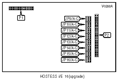
Upgrade connector 2 |
P1 |
|
Upgrade connector 1 |
J1 |
Upgrade connector 3 |
P2 |
|
Upgrade connector |
J2 |
|
|
|
Note:Connectors J1 and J2 interface with connectors P1 and P2. | |||
|
DRAM CONFIGURATION | |
|
Size |
Bank 0 |
|
512KB |
(2) 256K x 9 |
|
2MB |
(2) 1M x 9 |

|
RS-232 MODE SELECTION | |
|
Jumper |
RS-232 |
|
JP1/A-D |
Pins 1 & 2 closed |
|
JP2/A-D |
Pins 1 & 2 closed |
|
JP3/A-D |
Pins 1 & 2 closed |
|
JP4/A-D |
Pins 1 & 2 closed |
|
JP5/A-C |
Pins 1 & 2 closed |
|
JP6/A-C |
Pins 1 & 2 closed |
|
JP7/A-C |
Pins 1 & 2 closed |
|
JP8/A-C |
Pins 1 & 2 closed |
|
JP9/A-C |
Pins 1 & 2 closed |
|
JP10/A-C |
Pins 1 & 2 closed |
|
JP11/A-C |
Pins 1 & 2 closed |
|
JP12/A-C |
Pins 1 & 2 closed |
|
JP13/A-C |
Pins 1 & 2 closed |
|
JP14/A-C |
Pins 1 & 2 closed |
|
JP15/A-C |
Pins 1 & 2 closed |
|
JP16/A-C |
Pins 1 & 2 closed |
|
RS-422 MODE SELECTION | |
|
Jumper |
RS-422 |
|
JP1/A-C |
Pins 2 & 3 closed |
|
JP1/D |
Pins 1 & 2 closed |
|
JP2/A-C |
Pins 2 & 3 closed |
|
JP2/D |
Pins 1 & 2 closed |
|
JP3/A-C |
Pins 2 & 3 closed |
|
JP3/D |
Pins 1 & 2 closed |
|
JP4/A-C |
Pins 2 & 3 closed |
|
JP4/D |
Pins 1 & 2 closed |
|
JP5/A-C |
Pins 2 & 3 closed |
|
JP6/A-C |
Pins 2 & 3 closed |
|
JP7/A-C |
Pins 2 & 3 closed |
|
JP8/A-C |
Pins 2 & 3 closed |
|
JP9/A-C |
Pins 2 & 3 closed |
|
JP10/A-C |
Pins 2 & 3 closed |
|
JP11/A-C |
Pins 2 & 3 closed |
|
JP12/A-C |
Pins 2 & 3 closed |
|
JP13/A-C |
Pins 2 & 3 closed |
|
JP14/A-C |
Pins 2 & 3 closed |
|
JP15/A-C |
Pins 2 & 3 closed |
|
JP16/A-C |
Pins 2 & 3 closed |
|
MISCELLANEOUS TECHNICAL NOTE |
|
Serial ports are located on an interface box which connects to the Hostess I/E 8 via the 100-pin interface connector. |