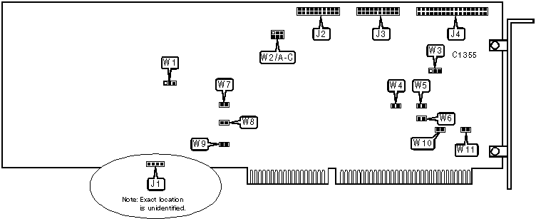
WESTERN DIGITAL CORPORATION
WD1006-WAH (VER. 2)
|
Chipset |
Western Digital |
|
Data Bus |
16-bit ISA |
|
Card Size |
Full height, full length |
|
Hard Drives Supported |
Two ST506/412(MFM) devices |
|
Floppy Drives Supported |
None |

|
CONNECTIONS | |||
|
Function |
Label |
Function |
Label |
|
4-pin drive active LED |
J1 |
20-pin data cable connector - drive 1 |
J3 |
|
20-pin data cable connector - drive 2 |
J2 |
34-pin control cable connector - hard drive |
J4 |
|
USER CONFIGURABLE SETTINGS | |||
|
Setting |
Label |
Position | |
| ╗ |
Drives up to 16 heads supported; reduced write current disabled |
W1 |
Pins 1 & 2 closed |
|
Drives up to 8 heads supported; reduced write current enabled |
W1 |
Pins 2 & 3 closed | |
| ╗ |
Card uses primary I/O address |
W3 |
Pins 1 & 2 closed |
|
Card uses secondary I/O address |
W3 |
Pins 2 & 3 closed | |
| ╗ |
Factory configured - do not alter |
W5 |
Open |
| ╗ |
Factory configured - do not alter |
W6 |
Open |
| ╗ |
Factory configured - do not alter |
W7 |
Open |
| ╗ |
Factory configured - do not alter |
W8 |
Open |
| ╗ |
Hard drive caching enabled |
W9 |
Open |
|
Hard drive caching disabled |
W9 |
Closed | |
| ╗ |
Signal ground not connected to chassis ground |
W11 |
Open |
|
Signal ground connected to chassis ground |
W11 |
Closed | |
|
WAIT STATE SELECTION | ||||
|
Setting |
W2/A |
W2/B |
W2/C | |
| ╗ |
Disabled |
Open |
Open |
Open |
| ╗ |
0 wait states |
Closed |
Open |
Open |
|
1 wait state |
Open |
Closed |
Open | |
|
2 wait states |
Open |
Open |
Closed | |
|
Note:On some versions of this board (designated F001), wait state circuitry is not included. Set these boards to the Disabled setting. All other boards should be set to one of the other three settings. | ||||
|
DRIVE LED CONFIGURATION | ||
|
Setting |
W4 |
W10 |
|
Non-latched; LED is on when drive is active |
Closed |
Open |
|
Latched; LED is on when drive is not active |
Open |
Closed |